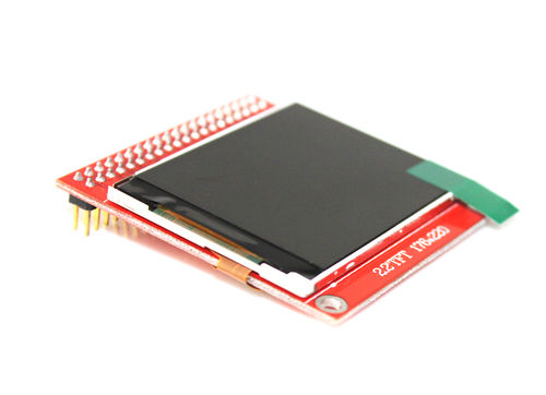
A while ago I bought a cheap little colour TFT display on eBay – the 2.2″ 176 x 220 pixel colour TFT01-2.2. It looked really good for a project I had in mind.
This little display is based on the S6D0164 controller, has a resolution of 176 x 220 pixels, and also has an SD card slot on the back of it. Best of all, it sells for around $5 on eBay!

I planned on using it with my Arduino Uno, but once it arrived I discovered this page saying that it couldn’t be used with the popular UTFT library. Even the UTFT page says they don’t recommend it be used with Uno, since it takes up so much RAM. D’oh!
I tried it anyway, and sure enough, the demo sketch that came with UTFT compiled to just over 32 KB (the Arduino Uno only has 32 KB of flash RAM). I tried commenting out half the demo, and that saved just enough space to be able to compile, download and run it. That’s a good sign, but it doesn’t leave any space for my own code.
I began poking around in the UTFT library files to see what the code was doing, and discovered the file memorysaver.h. That sounded promising!
The file contains a whole bunch of #defines that are commented out. The instructions in it say to uncomment all the lines for display controllers you don’t use, leaving only your one commented, and it will cause a bunch of controller-specific setup code to not be compiled into the library.
I gave it a go, and suddenly the full demo sketch only took up 19,524 bytes! Awesome! That leaves me with plenty of space for my own code. If you want to trim UTFT even further, there are some good tips in this Instructable – but it’s going to involve heavy editing of the library code.
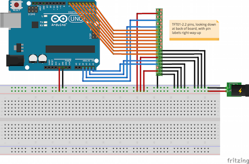
While trying to hook up this display, IÂ couldn’t find a single clear explanation of how it should be connected to the Arduino. Most people seemed to be using it with a shield. After reading through the UTFT code and looking at a few other sites, consulting the S6D0164 datasheet, and looking through the shield schematic, I found this setup to work well:

Be careful – make sure the version of the TFT01 you have is 5V friendly! Earlier versions only worked with 3.3V, so you’d need to use level-shifters (or a 3.3V Arduino variant).
I’ve used a big breadboard in that diagram, because I needed the space for more stuff I’m adding to the circuit for the project I’m working on. The DB0-DB7 pins possibly don’t need to be grounded (it worked fine for me without doing so), but the datasheet recommended it so I’ll err on the side of caution.
You need to disconnect digital pins 0 and 1 when you connect the Arduino to your computer to download a sketch, as they’re used for the serial connection. You also need to disconnect the 5V power pin when you connect it to your computer, as the Arduino will draw power from the USB.
I found that I needed to power both the Arduino and the display from the same power source. When the Arduino was powered by USB and the display by battery I had a lot of trouble, even after tying the grounds together. I don’t know what the problem was, but it was solved by powering everything from the battery (this is how it’ll be used when my project is finished, anyway).
In your code, when you instantiate the UTFT object, you’ll need to use these parameters to let it know what pins you’re using:
UTFT myGLCD(TFT01\_22, A5, A4, A3, A2);
I’m not using the SD card in the above diagram, but if you want to use it, it’ll require another 4 digital pins. Here’s a good reference for using SPI with Arduino and accessing SD cards using SPI. On the Uno, you’d connect SD\_CS to pin 10, SD\_MOSI to pin 11, SD\_SCK to pin 13, and SD\_MISO to pin 12.
If you find the above advice helpful, please let me know in the comments below! I’d love you to leave links to your own TFT01 projects as well.